In this lesson on logic gates and Boolean algebra, you'll explore fundamental concepts in computer science that help you understand how computers make decisions and process information at the hardware level. We'll cover the following main topics:
Let's start with the basics. Computers as super-smart machines that make decisions all the time, but at their core, they use something very simple: yes or no answers. This is where logic gates come in. Logic gates are like tiny decision-makers inside a computer's hardware. They take in simple inputs – which are just binary numbers, meaning 0 (for 'false' or 'off') or 1 (for 'true' or 'on') – and based on those, they produce an output that's also a 0 or 1.
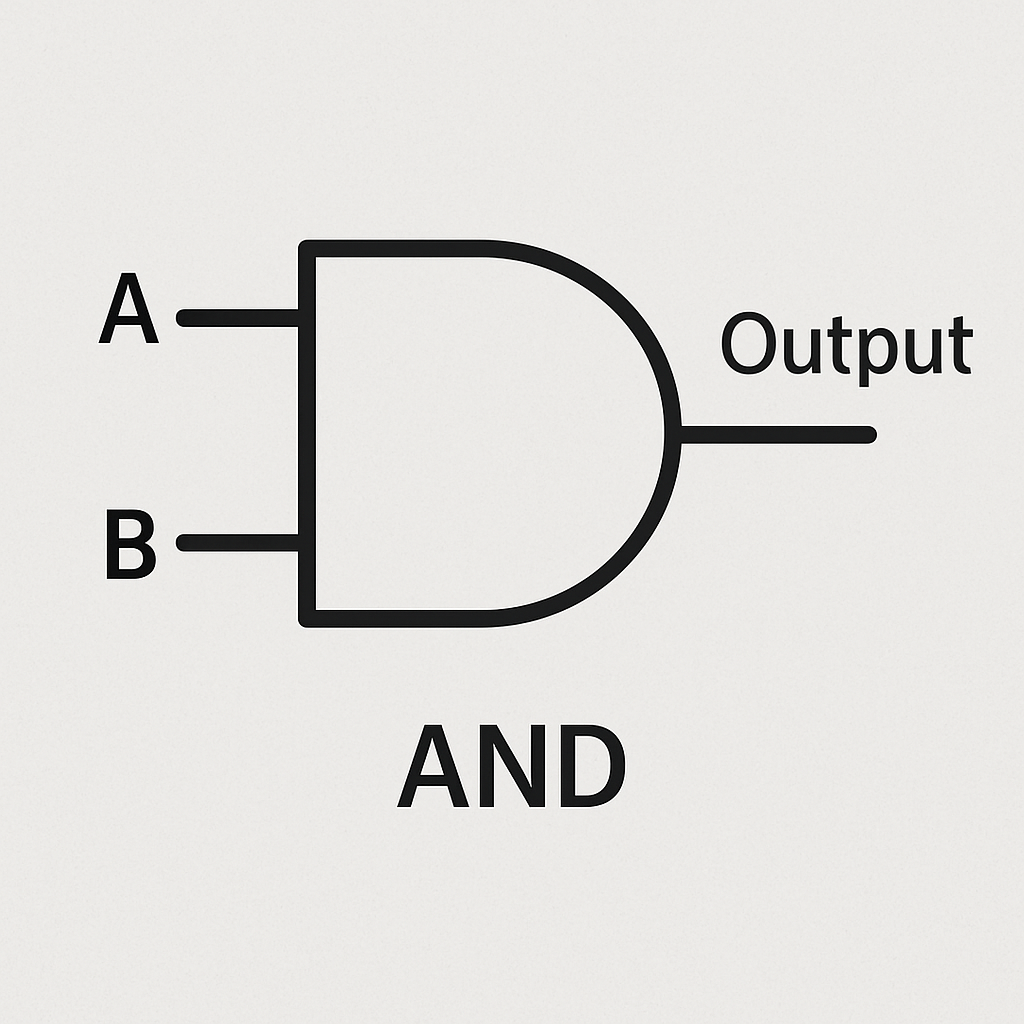
Think of binary like a light switch: off (0) or on (1). Logic gates process these switches to help the computer do everything from playing games to browsing the internet. There are three basic types of logic gates we'll focus on: AND, OR, and NOT. We'll explain each one with everyday examples to make it easier to understand.
These gates might seem basic, but when you combine lots of them, they create the complex circuits that power computers. For instance, they're used in the CPU (the brain of the computer) to do things like adding numbers or making choices in programs.
Let's understand what circuit diagrams and truth tables are.
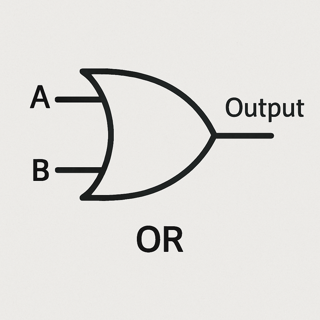
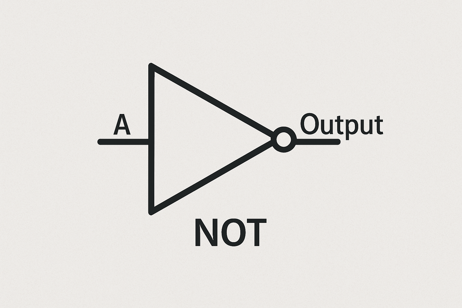
Circuit diagrams are like maps that show how electronic components, such as logic gates, are connected together to form a complete circuit. They use standard symbols to represent each type of gate, making it easier to visualise and design digital systems without needing the actual hardware.
Truth tables, on the other hand, are simple tables that list every possible combination of input values (0s and 1s) for a logic gate or circuit, along with the corresponding output. They help us verify how a gate behaves and are essential for understanding and designing logic circuits.
Now, let's look at the truth tables and circuit diagrams for the basic gates.
| A | B | Output (A AND B) |
|---|---|---|
| 0 | 0 | 0 |
| 0 | 1 | 0 |
| 1 | 0 | 0 |
| 1 | 1 | 1 |
| A | B | Output (A OR B) |
|---|---|---|
| 0 | 0 | 0 |
| 0 | 1 | 1 |
| 1 | 0 | 1 |
| 1 | 1 | 1 |
| A | Output (NOT A) |
|---|---|
| 0 | 1 |
| 1 | 0 |
Now lets create a simple program that uses if-then statements with AND and OR logical operators. These operators work just like the AND and OR gates in the previous step.
Open the MakeCode editor at makecode.microbit.org and start a new project.
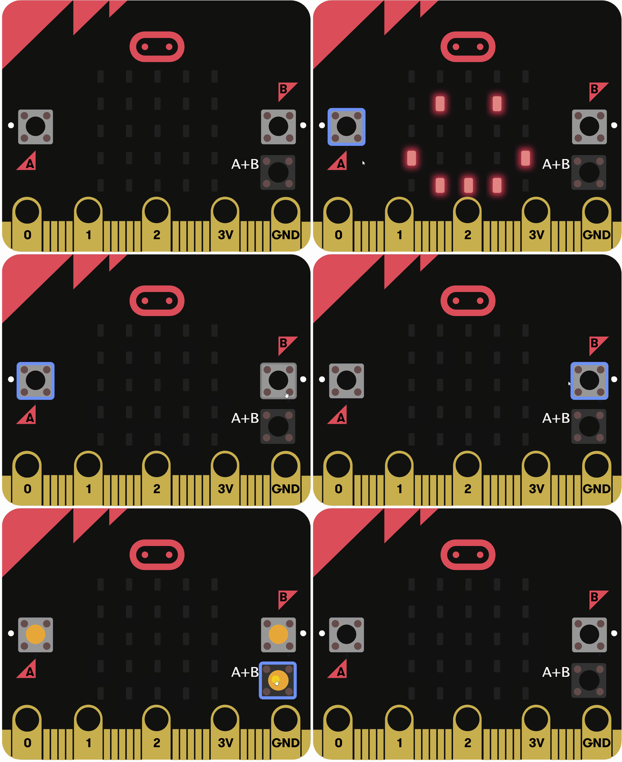
The goal is to create a program that checks button presses continuously and displays different icons based on logic conditions:
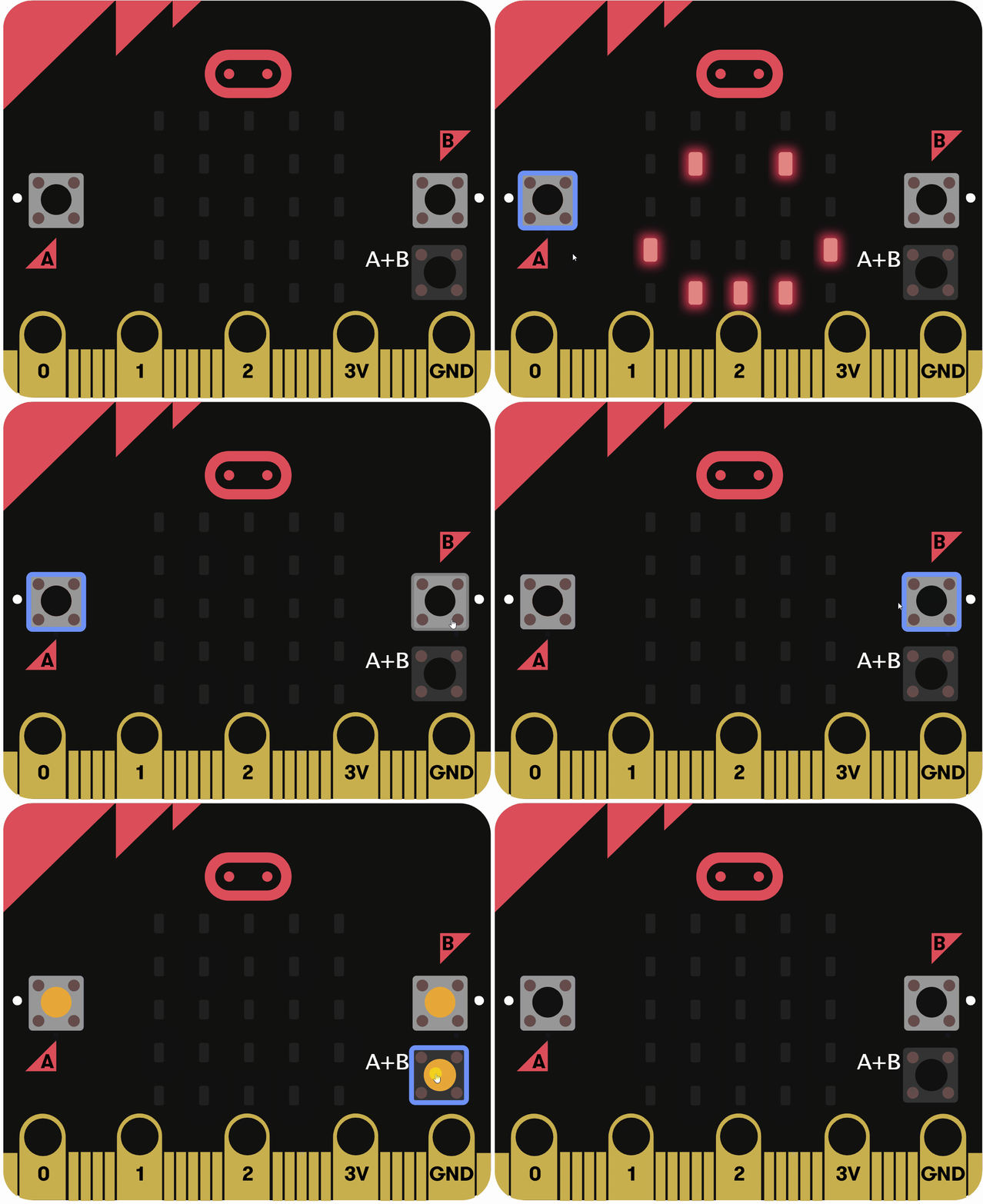
A AND button B are pressed, show a heart icon (simulating an AND gate).A OR button B is pressed, show a happy face icon (simulating an OR gate).This will run in a loop to constantly check the buttons.
This code simulates the gates by prioritising the AND condition first, so when both buttons are pressed, it shows the heart instead of the happy face.
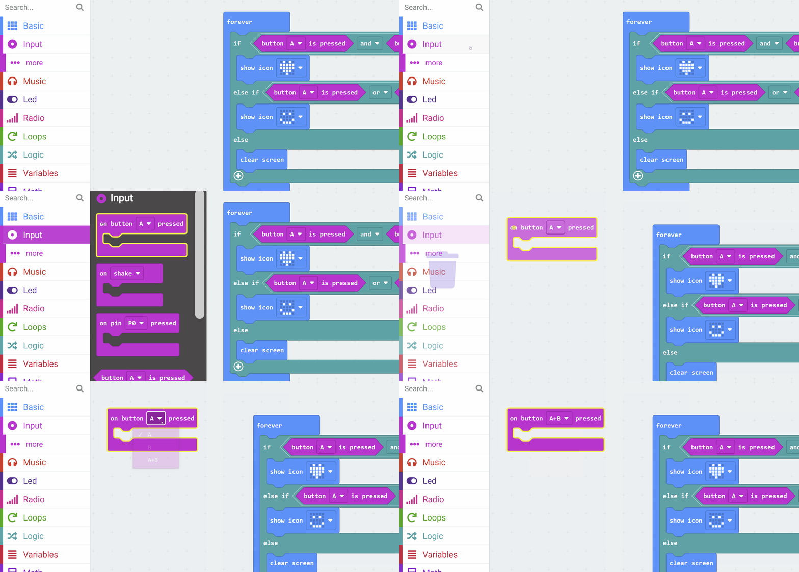
Add the following code:
input.onButtonPressed(Button.AB, function () { })basic.forever(function () { if (input.buttonIsPressed(Button.A) && input.buttonIsPressed(Button.B)) { basic.showIcon(IconNames.Heart) } else if (input.buttonIsPressed(Button.A) || input.buttonIsPressed(Button.B)) { basic.showIcon(IconNames.Happy) } else { basic.clearScreen() }})on button A+B pressed block so that the simulator displays the A+B button.Run the program in the simulator on the left side of the editor. Test it by clicking the button icons in the simulator:
OR is true).OR is true).AND is true).Think about how this matches the truth tables for AND and OR gates. The AND requires both inputs to be true (pressed), while OR needs at least one..
You're previewing this lesson. Get full access to this lesson and hundreds more — each one ready to teach, with interactive activities, printable resources and pupil progress tracking built in.